
1. Giriş
This manual provides detailed instructions for the installation, operation, and maintenance of your OLONETO 100A Solar Charge Controller. This device is designed to manage power flow from your solar panel to your battery bank and DC loads, ensuring efficient charging and protection for your battery system. It supports 12V, 24V, 36V, and 48V battery systems with automatic voltage identifikasiya.
Note: This controller utilizes a combination of MPPT and PWM charging technologies. It is not a 100% true MPPT controller.
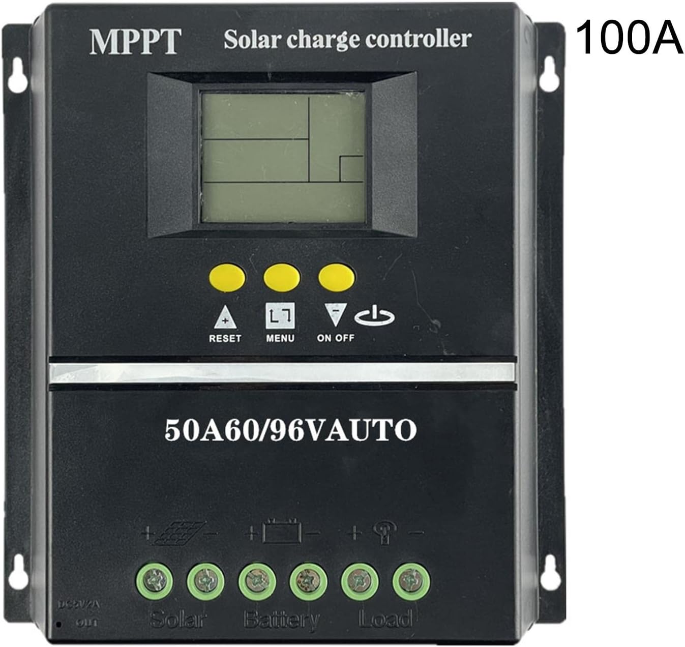
Şəkil 1: Ön view of the OLONETO 100A Solar Charge Controller, showing the LCD display, control buttons, and connection terminals. The "100A" rating is visible on the top right.
2. Təhlükəsizlik Təlimatları
- Ensure all connections are tight and correct to prevent damage to the controller or other components.
- Always connect the battery to the controller birinci, and then connect the solar panel. Disconnect in the reverse order: solar panel first, then battery. Failure to follow this sequence may damage the controller.
- Batareyanın həcminə əmin oluntage is sufficient for the controller to recognize the system voltage (e.g., >10V for 12V battery, >20V for 24V battery, >30V for 36V battery, >40V for 48V battery).
- Install the controller in a well-ventilated area, away from direct sunlight, high temperatures, and moisture.
- Do not attempt to repair or modify the controller yourself. Contact qualified personnel for service.
3. Məhsulun xüsusiyyətləri
The OLONETO Solar Charge Controller offers several key features for efficient solar power management:
- Avtomatik Cildtage İdentifikasiya: Automatically detects 12V, 24V, 36V, or 48V battery systems.
- LCD displey: Provides real-time information on battery status, charging parameters, and load status.
- İkili USB çıxışı: Convenient 5V output for charging mobile phones and other USB devices.
- Tənzimlənən Parametrlər: Allows users to customize charging and discharge settings.
- Smart Charge Management: Optimizes battery charging to prolong battery life.
- Ətraf Mühitin Mühafizəsi: Designed with green environmental protection principles.
- Automatic Focusing MPPT Tracking: High charging efficiency with non-stop detection during charging and bidirectional focusing tracking.

Figure 2: Diagram illustrating key features of the solar charge controller, including LCD display for battery power supply voltage, smart charge capabilities, 5V USB output, adjustable parameters, and green environmental protection.

Figure 3: Image highlighting the automatic focusing MPPT tracking feature, which ensures high charging efficiency and continuous detection during the charging process.
4. Quraşdırma və Quraşdırma
4.1 Wiring Sequence
- Batareyanı birləşdirin: Connect the battery to the controller's battery terminals. Ensure correct polarity (+ to + and - to -). The controller will automatically detect the battery voltage.
- Günəş panelini birləşdirin: Connect the solar panel to the controller's solar panel terminals. Ensure correct polarity.
- Connect the DC Load (Optional): Connect your DC loads to the controller's load terminals. Ensure correct polarity.
Important: Always follow this connection order: Battery → Solar Panel → Load. To disconnect, follow the reverse order: Load → Solar Panel → Battery.
4.2 Recommended Solar Panel Voltage
- üçün 12V battery systems: Use a solar panel with approximately 18V çıxış.
- üçün 24V battery systems: Use a solar panel with approximately 30-37V çıxış.
- üçün 36V battery systems: Use a solar panel with approximately 45-55V çıxış.
- üçün 48V battery systems: Use a solar panel with approximately 60-72V çıxış.
4.3 Naqillərin diaqramları

Figure 4: Basic wiring diagram showing connections for the solar panel, battery, and DC loads to the controller. Ensure positive (+) and negative (-) terminals are correctly matched.

Figure 5: Detailed wiring diagram illustrating connections for the solar panel, battery, DC load, and the integrated USB output for charging external devices.
5. Əməliyyat Təlimatları
5.1 Initial Power-Up and Display
Once the battery is connected, the controller's LCD display will power on, showing current system parameters. The controller automatically identifies the battery voltage (12V, 24V, 36V və ya 48V).
5.2 Düymə funksiyaları
- ▲ (Up/Reset): Used to increase values during setting, or as a reset function.
- Menyu: Used to navigate through display screens and enter/exit setting modes.
- ▼ (Down/On/Off): Used to decrease values during setting, or to toggle the DC load on/off.
5.3 Doldurma Cildtage Ayarlar
To adjust charging parameters:
- After connecting the battery, ensure the clock is set and saved (see 5.4 Clock Setting).
- " basıb saxlayın▲" button for 3-5 seconds. The screen will display "L**V" (floating charging voltagvə).
- İstifadə edin "▼" button to adjust the floating charging voltage.
- Briefly press "▲" again. The screen will display "H**V" (boost charging voltagvə).
- İstifadə edin "▼" button to adjust the boost charging voltage.
- Briefly press "▲" again. The screen will display "F**V" (low-voltage cut-off cildtage for DC load).
- İstifadə edin "▼" button to adjust the low-voltage cut-off cildtage.
- After making all desired adjustments, press and hold the "▲" button for 3-5 seconds to save the settings and exit.
5.4 Saat Parametrləri
To set the internal clock:
- Batareyanın qoşulduğundan əmin olun.
- " düyməsini basın▲"və ya"▼" buttons to navigate to the clock setting interface.
- İstifadə edin "▲"və"▼" buttons to adjust the time.
- Briefly press the "MENU" button (represented as "□" in some descriptions) to save the clock setting.
5.5 Load Protection Voltage İstinad
The following are typical battery charging voltages for different system voltages:
- İstifadə edərkən a 12V battery, the battery charging voltage is typically 13.7V.
- İstifadə edərkən a 24V battery, the battery charging voltage is typically 27.4V.
- İstifadə edərkən a 36V battery, the battery charging voltage is typically 41.1V.
- İstifadə edərkən a 48V battery, the battery charging voltage is typically 54.8V.
6. Baxım
- Daimi Yoxlama: Bütün naqil birləşmələrini vaxtaşırı möhkəmlik və korroziya üçün yoxlayın.
- Təmizlik: Kontrolleri təmiz, toz və zibildən təmiz saxlayın. Təmizləmək üçün quru bir parça istifadə edin.
- Havalandırma: Ensure the installation area remains well-ventilated to prevent overheating.
- Batareya Sağlamlığı: Monitor your battery's health and voltage regularly to ensure optimal system performance.
7. Giderme
| Problem | Mümkün Səbəb | Həll |
|---|---|---|
| Nəzarətçinin ekranı söndürülüb. | Batareya qoşulmayıb və ya batareya həcmi yoxdurtage çox aşağı. | Connect battery or ensure battery voltage is above minimum threshold (e.g., >10V for 12V system). |
| No charging from solar panel. | Solar panel not connected, incorrect polarity, or insufficient sunlight. | Check solar panel connections and polarity. Ensure adequate sunlight. |
| Cildtage identification error. | Batareya həcmitage was too low when connected initially. | Batareyanın həcmini təmin edintage is above the minimum threshold before connecting to the controller. Disconnect and reconnect the battery. |
| DC load not working. | Load is off, incorrect wiring, or battery voltage is below low-voltage kəsmə. | Check load connection and polarity. Press the "▼" button to toggle load. Check battery voltage and adjust low-voltage cut-off if necessary. |
8. Spesifikasiyalar
| Parametr | Dəyər |
|---|---|
| Model | 100A |
| Brend | OLONETO |
| Sistem Cildtage | 12V/24V/36V/48V Avtomatik |
| Doldurma Texnologiyası | MPPT/PWM Hybrid |
| USB çıxışı | Dual USB, 5V |
| Maddə Çəkisi | 200 qram |
| Ölçülər (təxminən) | 190 mm (7.48 düym) x 180 mm (7.08 düym) |

Figure 6: Physical dimensions of the solar charge controller, showing approximate measurements of 190mm (7.48 inches) in width and 180mm (7.08 inches) in height.
9. Zəmanət və Dəstək
For warranty information and technical support, please refer to the documentation provided with your purchase or contact your retailer. Keep your proof of purchase for any warranty claims.