1. Giriş
This instruction manual provides essential information for the safe and effective use of the UNI-T UPO1102 100MHz 2-Channel Digital Oscilloscope. The UPO1102 is a versatile instrument designed for electronic and electrical measurements, featuring a 100MHz bandwidth, 1 GSa/s real-time sample rate, 56 Mpts memory depth, and a 7-inch display. It incorporates Ultra Phosphor technology for enhanced waveform display and analysis capabilities.
Cihazın düzgün işləməsini təmin etmək və zədələnmənin qarşısını almaq üçün istifadə etməzdən əvvəl bu təlimatı diqqətlə oxuyun.
2. Təhlükəsizlik Məlumatı
Always observe the following safety precautions to avoid personal injury and prevent damage to the instrument or other connected devices.
- Elektrik kabelini lazımi şəkildə torpaqlanmış rozetkaya qoşun.
- Do not operate the oscilloscope in wet or damp şərtlər.
- Həddindən artıq istiləşmənin qarşısını almaq üçün düzgün havalandırma təmin edin.
- Do not open the instrument casing; xidməti ixtisaslı işçilərə həvalə edin.
- Use only specified probes and accessories.
- Observe all terminal ratings to prevent fire or shock hazard.
3. Məhsul bitdiview
3.1 Ön Panel
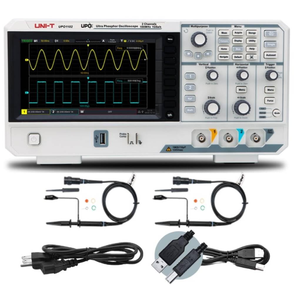
Figure 3.1: Front Panel of UPO1102 Oscilloscope
The front panel features the main display, various control knobs and buttons for waveform adjustment, trigger settings, and menu navigation. Input channels CH1 and CH2 are located at the bottom right.
3.2 Arxa Panel
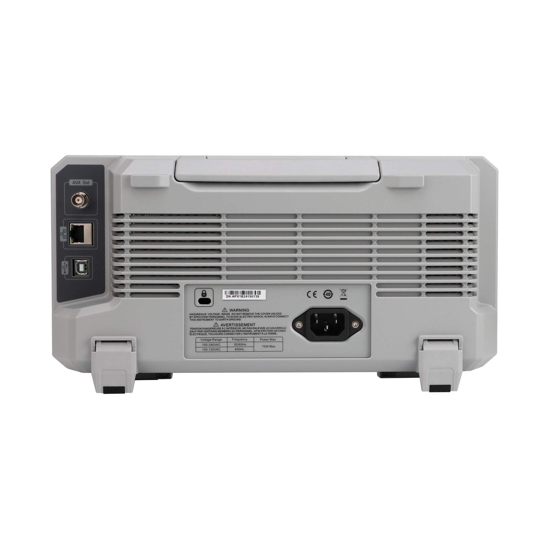
Figure 3.2: Rear Panel of UPO1102 Oscilloscope
The rear panel includes the AC power input, USB ports for data transfer and printing, and ventilation grilles to ensure proper cooling during operation.
3.3 Ölçülər
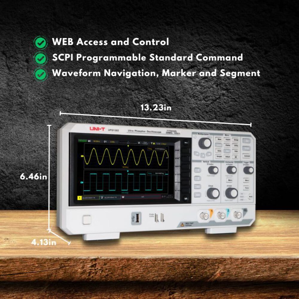
Figure 3.3: UPO1102 Oscilloscope Dimensions
The physical dimensions of the UPO1102 are approximately 13.23 inches (width) x 6.46 inches (height) x 4.13 inches (depth).
4. Quraşdırma
4.1 Qabın açılması və yoxlanılması
Upon receiving your UPO1102 oscilloscope, carefully unpack all components and inspect them for any signs of damage. Retain the packaging for future transport or storage.
Standart Aksesuarlar:
- Oscilloscope Probe (UT-P04) x 2
- Elektrik kabeli
- USB2.0 Printing Cable
- English Download Guide
- Multi-language Safety Manual
- Calibration Report (COC)
4.2 Enerji Bağlantısı
- Ensure the oscilloscope is placed on a stable, level surface with adequate ventilation.
- Connect the provided power cord to the AC power input on the rear panel of the oscilloscope.
- Elektrik kabelinin digər ucunu torpaqlanmış AC elektrik rozetkasına qoşun.
- Press the power button on the front panel to turn on the oscilloscope.
4.3 Zond Qoşulması və Kompensasiyası
Before taking measurements, it is crucial to compensate the probes to ensure accurate readings.
- Connect a probe to one of the input channels (CH1 or CH2) on the front panel.
- Connect the probe tip to the "Probe Comp" terminal and the ground clip to the ground terminal next to it.
- düyməsini basın Avtomatik button. The oscilloscope will automatically adjust the settings to display the compensation signal.
- Observe the square wave displayed on the screen. If the waveform is not a perfect square (over-compensated or under-compensated), adjust the trimmer on the probe body using a non-metallic tool until a flat-top square wave is achieved.
- Repeat for the second probe if using both channels.

Figure 4.1: Probe Compensation Waveform
A correctly compensated probe displays a clean square wave. Adjust the probe's trimmer if the waveform shows overshoot or undershoot.
5. Əməliyyat Təlimatları
5.1 Əsas idarəetmə vasitələri
- Güc düyməsi: Located on the front panel, used to turn the device on or off.
- Multipurpose Knob: Used for menu navigation and parameter adjustment. Press to confirm selections.
- Vertical Controls (CH1, CH2): Adjust vertical position and scale (volts/division) for each channel. "Push to Zero" resets position, "Push to Fine" enables fine adjustment.
- Horizontal Controls: Adjust horizontal position and time base (seconds/division). "Push to Zero" resets position, "Push to Zoom" enables horizontal zoom.
- Tetikleyici Nəzarətlər: Set the trigger level, mode (Auto, Normal, Single), and force a trigger event.
- Avtomatik Düymə: Sabit dalğa formasını göstərmək üçün şaquli, üfüqi və tetik parametrlərini avtomatik tənzimləyir.
- Run/Stop Button: Dalğa formasının əldə edilməsinə başlayır və ya dayandırır.
5.2 Waveform Acquisition and Display
The UPO1102 features a 7-inch display and Ultra Phosphor technology for clear waveform visualization, even with complex signals.

Figure 5.1: Ultra Phosphor Display
Ultra Phosphor technology provides a gradient display, where brighter areas indicate more frequent occurrences of the waveform, helping to visualize signal anomalies and variations.

Figure 5.2: Multi-Channel Waveform Display
The UPO1102 can display and analyze two channels simultaneously, allowing for comparison of different signals.
5.3 Ölçmə Funksiyaları
- Kursorun ölçülməsi: Activate the "Cursor" function to measure time and voltage parameters within a specified area on CH1, CH2, MATH, or REF waveforms.
- FFT Təhlili: The UPO1102 features 1Mpts FFT sampling points, enabling frequency domain analysis. Access the FFT function to set frequency range, detection mode, and spectrum marking.
- Navigation Functions: Utilize time navigation, marker navigation, and segment navigation for detailed waveform inspection.

Figure 5.3: FFT Spectrum Analysis
The FFT function transforms time-domain signals into the frequency domain, useful for analyzing harmonic content and noise.
5.4 Digital Decoding
The innovative hardware decoding feature allows for real-time decoding of serial bus protocols. With a deep storage of 56 Mpts, decoding speed is maintained at millisecond levels, preventing delays when viewing decoded data. This function does not affect the waveform refresh rate, maintaining the digital fluorescence display effect.

Figure 5.4: Digital Decoding Example
The decoding feature displays protocol information directly on the screen, simplifying debugging of serial communications.
5.5 Data Storage and Connectivity
- Yaddaş Dərinliyi: The UPO1102 offers a 56 Mpts memory depth, allowing for capture of long signal durations at high sample dərəcələri.
- USB Bağlantısı: Use the provided USB2.0 printing cable to connect the oscilloscope to a computer for data transfer or direct printing.
- Web Access and Control: Cihaz dəstəkləyir WEB access and control, along with SCPI (Standard Commands for Programmable Instruments) for remote operation and automation.

Figure 5.5: Memory Depth Indication
A large memory depth is crucial for capturing transient events or long sequences of data without losing detail.
6. Baxım
6.1 Ümumi qulluq
- Keep the instrument clean and dry. Avoid operating in dusty or humid environments.
- Protect the display from scratches and impacts.
- Do not block the ventilation openings on the rear panel.
6.2 Təmizləmə
To clean the exterior of the oscilloscope:
- Disconnect the power cord and all probes/cables.
- Yumşaq parça istifadə edin dampened with mild detergent and water. Do not use abrasive cleaners or solvents.
- For the display, use a soft, lint-free cloth specifically designed for electronic screens.
- Ensure the instrument is completely dry before reconnecting power.
7. Giderme
This section addresses common issues you might encounter with the UPO1102 oscilloscope. For problems not listed here, contact UNI-T customer support.
| Problem | Mümkün Səbəb | Həll |
|---|---|---|
| Açıldıqdan sonra ekran yoxdur. | Power cord not connected, power outlet faulty, instrument fault. | Check power cord connection. Test power outlet. If problem persists, contact support. |
| Heç bir dalğa forması göstərilmir. | Probe not connected, signal too small/large, trigger not set correctly, channel off. | Ensure probe is connected to signal source. Press Avtomatik button. Adjust vertical scale (Volts/Div) and horizontal scale (Sec/Div). Check trigger level. Ensure channel is enabled. |
| Unstable waveform. | Trigger level incorrect, trigger mode unsuitable, signal noise. | Adjust trigger level. Try different trigger modes (e.g., Normal or Single). Reduce noise in the signal path. |
| Incorrect measurements. | Probe compensation incorrect, probe attenuation setting wrong, measurement settings incorrect. | Perform probe compensation (Section 4.3). Verify probe attenuation setting matches physical probe (e.g., 1X, 10X). Check measurement parameters. |
8. Spesifikasiyalar
| Parametr | Dəyər |
|---|---|
| Bant genişliyi | 100 MHz |
| Kanallar | 2 |
| Real vaxtda S.ampdərəcəsi | 1 GSa/s |
| Yaddaş Dərinliyi | 56 Mpts |
| Waveform Capture Rate | 500,000 wfm/s |
| Ekran | 7 düym |
| FFT Sampling Points | 1 Mpts |
| Məhsul Ölçüləri | 13 x 4 x 6 düym (təxminən 330 x 102 x 152 mm) |
| Maddə Çəkisi | 8.13 funt (təqribən 3.69 kq) |
| İstehsalçı | UNI-T |
| ASIN | B0D7F2D9MS |
| İlk Əlçatan Tarix | 19 iyun 2024-cü il |
9. Zəmanət və Dəstək
For warranty information, technical support, or service inquiries regarding your UNI-T UPO1102 oscilloscope, please refer to the official UNI-T websaytına daxil olun və ya müştəri xidməti şöbəsi ilə əlaqə saxlayın.
UNI-T Rəsmi Mağazası: Amazonda UNI-T Mağazasına baş çəkin
Please have your product model (UPO1102) and ASIN (B0D7F2D9MS) available when contacting support.


